Introduction
Use case diagrams are an essential part of software engineering and systems analysis. They provide a graphical representation of the functional requirements of a system from the perspective of its users. This guide will explain the key concepts related to use case diagrams, including actors, use cases, associations, includes, extends, and extension points. We will use the attached use case diagram as an example to illustrate these concepts and provide guidelines, tips, and tricks for creating effective use case diagrams.
Example Diagram
Key Concepts in Use Case Diagrams
Actors
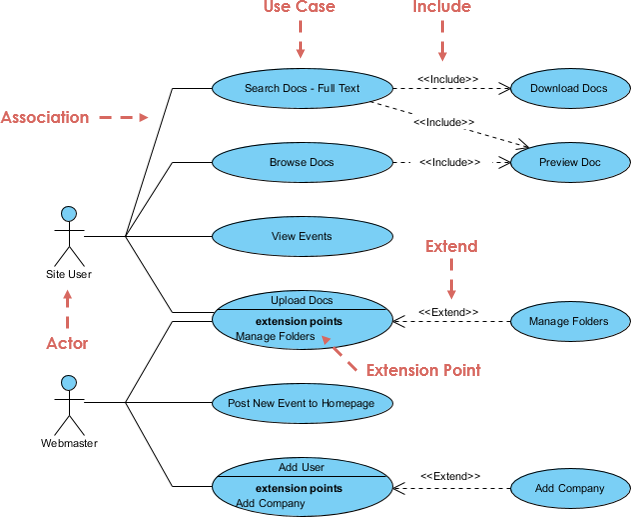
Actors represent the users or external systems that interact with the system. They can be individuals, groups, or other systems that have a specific role in the system’s functionality. In the attached diagram, the actors are:
- Site User: A general user who interacts with the system to search, browse, and view documents and events.
- Webmaster: A user with administrative privileges who manages the system, adds users, and posts new events.
Use Cases
Use cases represent the functional requirements or behaviors of the system. They describe the interactions between actors and the system to achieve specific goals. In the attached diagram, the use cases are:
- Search Docs – Full Text: Allows the site user to search for documents using full-text search.
- Browse Docs: Allows the site user to browse through the available documents.
- View Events: Allows the site user to view events.
- Upload Docs: Allows the site user to upload documents to the system.
- Post New Event to Homepage: Allows the webmaster to post new events to the homepage.
- Add User: Allows the webmaster to add new users to the system.
Associations
Associations represent the relationships between actors and use cases. They indicate that an actor participates in a use case. In the attached diagram, the associations are:
- Site User is associated with Search Docs – Full Text, Browse Docs, View Events, and Upload Docs.
- Webmaster is associated with Post New Event to Homepage and Add User.
Include Relationships
Include relationships represent a situation where one use case includes the behavior of another use case. This means that the included use case is always part of the base use case. In the attached diagram, the include relationships are:
- Search Docs – Full Text includes Download Docs and Preview Doc.
- Browse Docs includes Preview Doc.
Extend Relationships
Extend relationships represent a situation where one use case extends the behavior of another use case under certain conditions. This means that the extending use case is optional and only occurs under specific conditions. In the attached diagram, the extend relationships are:
- Upload Docs extends to Manage Folders.
- Add User extends to Add Company.
Extension Points
Extension points are specific points in a use case where the behavior can be extended by other use cases. They define where and how the extending use case can modify the base use case. In the attached diagram, the extension points are:
- Upload Docs has an extension point for Manage Folders.
- Add User has an extension point for Add Company.
Guidelines for Creating Effective Use Case Diagrams
1. Identify Actors
- Start by identifying all the actors that will interact with the system.
- Consider both primary and secondary actors. Primary actors initiate interactions, while secondary actors provide services or information.
2. Define Use Cases
- For each actor, define the use cases that represent the goals they want to achieve with the system.
- Use clear and concise names for use cases that describe the action or goal.
3. Establish Associations
- Draw associations between actors and use cases to show which actors participate in which use cases.
- Use solid lines to represent associations.
4. Use Include Relationships
- Identify common behaviors that are part of multiple use cases and create include relationships.
- Use dashed lines with the «include» stereotype to represent include relationships.
5. Use Extend Relationships
- Identify optional behaviors that can extend the base use case under specific conditions and create extend relationships.
- Use dashed lines with the «extend» stereotype to represent extend relationships.
6. Define Extension Points
- Identify specific points in a use case where the behavior can be extended by other use cases.
- Use extension points to define where and how the extending use case can modify the base use case.
Tips and Tricks
1. Keep It Simple
- Avoid overcomplicating the diagram by including too many details.
- Focus on the main interactions and goals of the actors.
2. Use Consistent Naming
- Use consistent and descriptive names for actors and use cases.
- Avoid using technical jargon that may confuse stakeholders.
3. Iterate and Refine
- Start with a high-level diagram and iteratively refine it as you gather more information.
- Review and update the diagram regularly to ensure it remains accurate and relevant.
4. Collaborate with Stakeholders
- Involve stakeholders in the creation and review of the use case diagram to ensure it meets their needs and expectations.
- Use the diagram as a communication tool to facilitate discussions and clarify requirements.
5. Use Tools and Templates
- Use diagramming tools like Visual Paradigm to create professional-looking use case diagrams.
- Use templates and examples as a starting point to save time and ensure consistency.
Conclusion
Use case diagrams are a powerful tool for capturing and communicating the functional requirements of a system. By understanding the key concepts of actors, use cases, associations, includes, extends, and extension points, you can create effective use case diagrams that help in designing, developing, and testing software systems. The attached use case diagram serves as an example to illustrate these concepts and provides guidelines, tips, and tricks for creating comprehensive and clear use case diagrams.
Use Case Diagram References
Here is a reference list on use case diagrams using the Visual Paradigm UML tool, with URLs embedded under the article titles:
-
Introduction to UML Diagrams in Visual Paradigm – ArchiMetric
-
Online Use Case Diagram Tool
-
Free UML Tool
-
Free Use Case Diagram Tool
-
How to Draw Use Case Diagram?
-
Use Case Description in Visual Paradigm for UML
-
Use Case Diagram – UML 2 Diagrams – UML Modeling Tool
-
Online UML Diagram Tool
These references provide a comprehensive overview of creating and using use case diagrams with the Visual Paradigm UML tool.
