Class diagrams are one of the most fundamental and widely used types of diagrams in Unified Modeling Language (UML). They provide a static view of a system by illustrating the structure, relationships, and attributes of classes within the system. Class diagrams are essential for designing, understanding, and documenting object-oriented systems. In this article, we will explore why class diagrams are so important, how they are used in conjunction with other UML diagrams, and when they are most effectively utilized.
What is a Class Diagram?
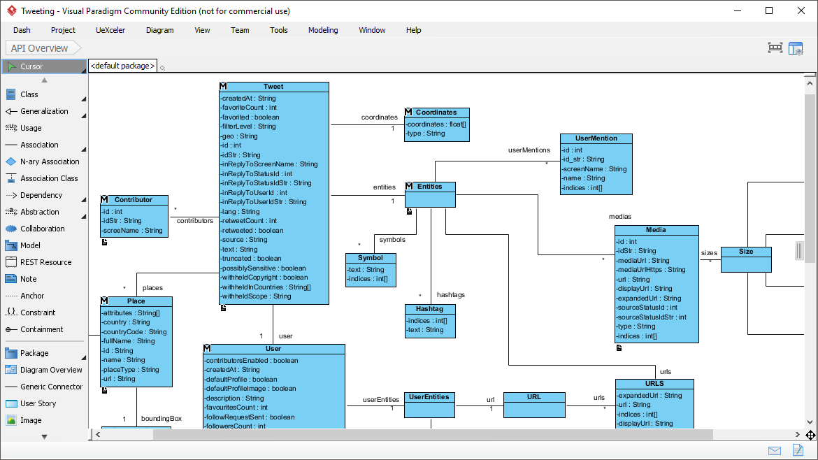
A class diagram is a type of UML diagram that represents the structure of a system by showing its classes, attributes, methods, and the relationships between these classes. Each class is represented as a rectangle divided into three compartments:
- Class Name: The top compartment contains the name of the class.
- Attributes: The middle compartment lists the attributes (properties or fields) of the class.
- Methods: The bottom compartment lists the methods (operations or functions) of the class.
Relationships between classes, such as inheritance, association, aggregation, and composition, are depicted using lines and arrows.
Why Are Class Diagrams So Important?
Class diagrams play a critical role in software development for several reasons:
1. Visual Representation of System Structure
Class diagrams provide a clear and concise visual representation of the system’s structure. They help developers and stakeholders understand the system’s design at a glance, making it easier to identify key components and their interactions.
2. Foundation for Object-Oriented Design
Class diagrams are the backbone of object-oriented design. They help in defining classes, their attributes, and methods, which are the building blocks of an object-oriented system. By modeling classes and their relationships, developers can ensure that the system adheres to object-oriented principles such as encapsulation, inheritance, and polymorphism.
3. Facilitates Communication
Class diagrams serve as a common language between developers, designers, and stakeholders. They bridge the gap between technical and non-technical team members by providing a visual representation of the system that is easy to understand.
4. Supports Code Generation
Many modern development tools can generate code directly from class diagrams. This not only saves time but also ensures consistency between the design and implementation. Conversely, class diagrams can also be reverse-engineered from existing code to document the system.
5. Identifies Design Flaws Early
By modeling the system before implementation, class diagrams help identify potential design flaws, such as redundant classes, missing relationships, or incorrect inheritance hierarchies. This early detection reduces the risk of costly changes during later stages of development.
6. Documentation and Maintenance
Class diagrams serve as valuable documentation for the system. They provide a reference for developers to understand the system’s structure, making it easier to maintain and extend the system over time.
How Class Diagrams Are Used with Other UML Diagrams
Class diagrams are rarely used in isolation. They are often used in conjunction with other UML diagrams to provide a comprehensive view of the system. Here are some examples:
1. Use Case Diagrams
Use case diagrams describe the functional requirements of a system by showing interactions between actors and use cases. Class diagrams complement use case diagrams by defining the classes and relationships needed to implement the use cases.
- How: After identifying the use cases, developers create class diagrams to model the classes required to fulfill those use cases.
- When: During the requirements analysis and design phases.
2. Sequence Diagrams
Sequence diagrams depict the interaction between objects in a system over time. They focus on the flow of messages between objects.
- How: Class diagrams provide the structure of the classes involved in the sequence diagram. The objects in the sequence diagram are instances of the classes defined in the class diagram.
- When: During the design phase to model dynamic behavior.
3. Activity Diagrams
Activity diagrams represent the workflow or process flow within a system. They show the sequence of activities and decisions.
- How: Class diagrams define the classes and methods that perform the activities depicted in the activity diagram.
- When: During the design phase to model business processes or complex workflows.
4. State Machine Diagrams
State machine diagrams model the behavior of objects as they transition through different states in response to events.
- How: Class diagrams define the classes and attributes that represent the states and transitions in the state machine diagram.
- When: During the design phase to model state-dependent behavior.
5. Component and Deployment Diagrams
Component diagrams show the physical components of a system, while deployment diagrams show how these components are deployed on hardware.
- How: Class diagrams define the logical structure of the components, which are then mapped to physical components in the component and deployment diagrams.
- When: During the design and implementation phases.
When to Use Class Diagrams
Class diagrams are most effective in the following scenarios:
- During the Design Phase: Class diagrams are used to model the system’s structure before implementation begins. They help in defining the classes, attributes, methods, and relationships.
- When Documenting a System: Class diagrams are used to create documentation for an existing system, making it easier for new developers to understand the system.
- When Refactoring or Extending a System: Class diagrams help identify areas of the system that need refactoring or extension by providing a clear view of the existing structure.
- During Team Collaboration: Class diagrams are used to communicate design ideas and decisions among team members.
Conclusion
Class diagrams are an indispensable tool in software development. They provide a clear and structured representation of a system’s design, making it easier to understand, communicate, and implement. When used in conjunction with other UML diagrams, class diagrams offer a comprehensive view of the system, ensuring that both its static structure and dynamic behavior are well-defined. Whether you are designing a new system, documenting an existing one, or collaborating with a team, class diagrams are a vital part of the software development process.
References
Here is a reference list with embedded URLs on the topic of UML using the Visual Paradigm tool:
-
Free UML Tool
- Description: Visual Paradigm offers a free UML tool that supports various UML diagram types, including sequence diagrams and requirement diagrams. It is designed for ease of use and high-quality outcomes.
- URL: Free UML Tool 1
-
What is Unified Modeling Language (UML)?
- Description: This guide provides an introduction to UML and explains how Visual Paradigm Community Edition can help learn UML faster and more effectively. It supports all UML diagram types and is an award-winning, easy-to-use tool.
- URL: What is Unified Modeling Language (UML)? 2
-
Online UML Diagram Tool
- Description: Visual Paradigm Online is a powerful UML diagramming tool that supports various UML diagrams such as Class, Use Case, Sequence, Activity, Deployment, Component, State Machine, and Package Diagrams. It features on-the-fly UML syntax checks and a user-friendly interface.
- URL: Online UML Diagram Tool 3
-
UML Class Diagram Tutorial
- Description: This tutorial provides a comprehensive guide to creating UML Class Diagrams using Visual Paradigm. It explains the concepts and steps involved in drawing a Class Diagram.
- URL: UML Class Diagram Tutorial 4
-
Visual Paradigm
- Description: Visual Paradigm is an all-in-one modeling platform that supports UML, BPMN, DFD, ERD, SysML, and other diagrams. It offers a suite of design, analysis, and management tools for IT project development and digital transformation.
- URL: Visual Paradigm 5
-
UML Practical Guide
- Description: This guide provides a practical introduction to UML modeling using Visual Paradigm. It explains how UML can be used to visualize, specify, construct, and document software systems.
- URL: UML Practical Guide 6
-
Best UML & BPMN Tool – Visual Paradigm Modeler
- Description: Visual Paradigm Modeler is an award-winning UML modeling tool that supports UML, Requirement Diagram, BPMN, ERD, DFD, and more. It makes modeling easy and fast.
- URL: Best UML & BPMN Tool – Visual Paradigm Modeler 7
-
Introduction to UML Diagrams in Visual Paradigm
- Description: This article introduces the various types of UML diagrams supported by Visual Paradigm, including Class Diagrams, Profile Diagrams, and more. It explains how UML diagrams help in understanding complex structures and interactions.
- URL: Introduction to UML Diagrams in Visual Paradigm 8
-
Best UML, SysML & ERD Tool
- Description: Visual Paradigm offers a free UML, SysML, and ERD tool that supports various diagram types. It is a one-stop shop for creating UML diagrams, SysML diagrams, and ERDs.
- URL: Best UML, SysML & ERD Tool 9
-
Visual Paradigm Online – Google Workspace Marketplace
- Description: Visual Paradigm Online is a leading visual modeling and diagramming platform for team collaboration. It supports the creation of UML diagrams, flowcharts, ERDs, BPMN diagrams, and more.
- URL: Visual Paradigm Online – Google Workspace Marketplace 10
These references provide a comprehensive overview of UML and its implementation using the Visual Paradigm tool.
