Overview of the 14 UML Diagram Types
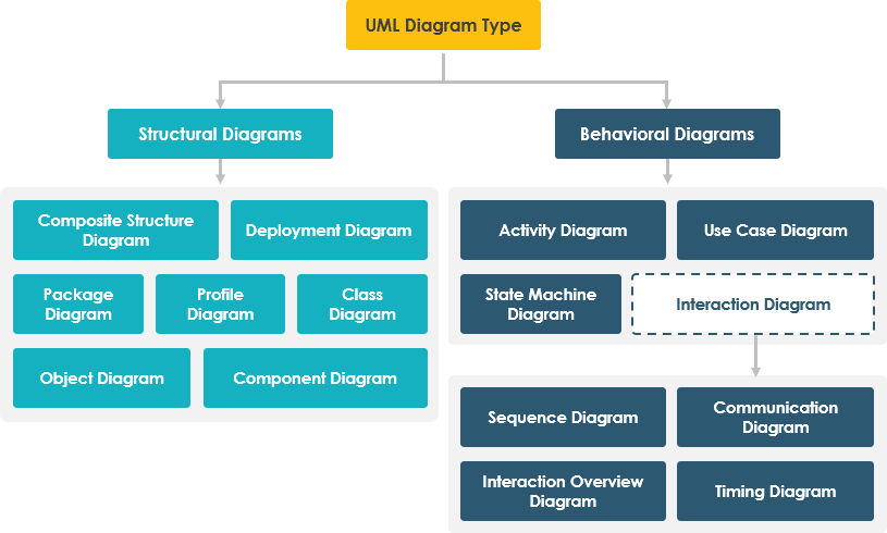
The Unified Modeling Language (UML) is a standardized general-purpose modeling language managed by the Object Management Group (OMG). It provides a set of graphic notation techniques to create visual models for software-intensive systems. UML 2.2 includes 14 types of diagrams, categorized into structural and behavioral diagrams.

Structural UML Diagrams
Structural UML diagrams represent the static aspects of a system. There are seven types of structural diagrams:
- Class Diagram: Shows the static structure of a system, including classes, attributes, methods, and relationships between classes.
- Object Diagram: Similar to class diagrams but represents a snapshot of the detailed state of a system at a specific point in time.
- Component Diagram: Illustrates the organization and dependencies among a set of components, such as source code components, binary code components, or executable components.
- Deployment Diagram: Shows the physical nodes of a system and the components that run on those nodes.
- Package Diagram: Organizes the elements of a model by grouping them into packages.
- Composite Structure Diagram: Shows the internal structure of a class and the collaborations that this structure makes possible.
- Profile Diagram: Provides a generic extension mechanism for customizing UML models for particular domains or platforms.
Behavioral UML Diagrams
Behavioral UML diagrams represent the dynamic aspects of a system. There are seven types of behavioral diagrams, including four that represent different aspects of interactions:
- Use Case Diagram: Captures the functional requirements of a system by illustrating the interactions between actors (users) and the system.
- Sequence Diagram: Shows how objects interact in a particular scenario of a use case, focusing on the time-ordering of messages.
- Activity Diagram: Represents the workflows of stepwise activities and actions, similar to flowcharts.
- State Machine Diagram: Illustrates the states of an object and the transitions between states due to events.
- Communication Diagram: Also known as collaboration diagrams, they show the interactions between objects in terms of sequenced messages.
- Interaction Overview Diagram: Provides a high-level view of interactions, combining elements from activity diagrams and interaction diagrams.
- Timing Diagram: Shows the interactions between objects in a particular scenario, with a focus on time constraints.
Is UML Too Complex?
UML is indeed a vast topic, with a large volume of diagramming notation grouped into 14 different diagram types. Each diagram serves different purposes and addresses various aspects of software development needs. The UML specification is over 700 pages long, which can be overwhelming and may negatively impact its perception and adoption.
However, according to Grady Booch, one of the key developers of UML, “For 80% of all software, only 20% of UML is needed.” This suggests that while UML is comprehensive, not all of its features are necessary for most projects.
Interpreting the UML Survey Results
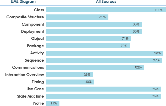
The UML survey results provide valuable insights into the usage of various UML diagrams in software development projects. By categorizing the diagrams based on their usage frequency, we can identify which diagrams are widely used and which are scarcely used. This information can help in developing a focused learning plan and in understanding the relevance of each diagram in agile environments.
Widely Used UML Diagrams (≥ 60% of sources)

- Class Diagram (100%): Essential for modeling the static structure of a system, including classes, attributes, methods, and relationships.
- Activity Diagram (98%): Useful for representing workflows of stepwise activities and actions, similar to flowcharts.
- Sequence Diagram (97%): Shows how objects interact in a particular scenario, focusing on the time-ordering of messages.
- Use Case Diagram (96%): Captures the functional requirements of a system by illustrating the interactions between actors (users) and the system.
- State Machine Diagram (96%): Illustrates the states of an object and the transitions between states due to events.
- Component Diagram (80%): Illustrates the organization and dependencies among a set of components.
- Deployment Diagram (80%): Shows the physical nodes of a system and the components that run on those nodes.
- Package Diagram (70%): Organizes the elements of a model by grouping them into packages.
- Object Diagram (71%): Represents a snapshot of the detailed state of a system at a specific point in time.
- Communications Diagram (62%): Shows the interactions between objects in terms of sequenced messages.
Scarcely Used UML Diagrams (≤ 40% of sources)
- Profile Diagram (11%): Provides a generic extension mechanism for customizing UML models for particular domains or platforms.
- Timing Diagram (40%): Shows the interactions between objects in a particular scenario, with a focus on time constraints.
- Interaction Overview Diagram (39%): Provides a high-level view of interactions, combining elements from activity diagrams and interaction diagrams.
- Composite Structure Diagram (52%): Shows the internal structure of a class and the collaborations that this structure makes possible. Although it is used by more than 40% of sources, it is less commonly used compared to other diagrams.
Discussion and Review
The survey results indicate that certain UML diagrams are more widely adopted than others. This can be attributed to their simplicity, versatility, and relevance to common software development tasks. For example, Class Diagrams and Use Case Diagrams are fundamental for understanding the structure and requirements of a system, respectively.
On the other hand, diagrams like Profile Diagrams and Timing Diagrams are less frequently used, possibly due to their specialized nature and the complexity they add to the modeling process.
Recommendations
- Focus on Essential Diagrams: For most software development projects, focusing on the widely used diagrams such as Class, Activity, Sequence, Use Case, and State Machine Diagrams can provide a solid foundation for modeling.
- Adapt to Agile Practices: In agile environments, it is crucial to use UML diagrams selectively and efficiently. Choose diagrams that provide the most value with the least overhead. For example, Use Case Diagrams can help in understanding requirements quickly, while Activity Diagrams can be used for workflow modeling.
- Learning Plan: Develop a learning plan that prioritizes the widely used diagrams. Start with Class, Activity, and Sequence Diagrams, and gradually incorporate other diagrams as needed.
- Tool Support: Use tools like Visual Paradigm Community Edition, which supports all UML diagram types and can help in learning and drawing UML diagrams effectively.
The UML survey results provide a clear picture of the most and least used UML diagrams. By focusing on the widely used diagrams and adapting UML practices to agile methodologies, teams can leverage the benefits of UML without being overwhelmed by its complexity. This approach ensures that UML remains relevant and valuable in today’s dynamic software development landscape.
Is UML Still Relevant in Today’s Dynamic World?
The relevance of UML in today’s fast-paced and agile software development environment is a topic of debate. While some argue that UML’s comprehensive nature makes it too cumbersome for agile teams, others see its value in providing a standardized language for modeling complex systems.
Agility and UML
Agile methodologies emphasize flexibility, quick iterations, and continuous improvement. UML, with its detailed and structured approach, might seem at odds with these principles. However, UML can be adapted to fit agile practices. For instance, using a subset of UML diagrams that are most relevant to the project can streamline the modeling process without sacrificing clarity.
Benefits of UML in Agile Teams
- Communication: UML provides a common language for developers, architects, and stakeholders to communicate complex ideas effectively.
- Documentation: Even in agile environments, some level of documentation is necessary. UML diagrams can serve as living documents that evolve with the project.
- Design Clarity: UML can help in visualizing and understanding the system architecture, making it easier to identify potential issues early in the development process.
Challenges of UML in Agile Teams
- Time-Consuming: Creating and maintaining UML diagrams can be time-consuming, which might not align with the rapid pace of agile development.
- Complexity: The comprehensive nature of UML can be overwhelming for teams that prefer lighter, more flexible tools.
- Adaptation: Agile teams need to be selective about which UML diagrams to use and how to integrate them into their workflow to avoid unnecessary overhead.
Essential UML Diagrams
Based on a UML survey, the usage of UML diagrams can be categorized as follows:
- Widely Used (≥ 60% of sources): These diagrams are commonly used in most projects.
- Scarcely Used (≤ 40% of sources): These diagrams are less frequently used.
For example, the Activity Diagram is widely used in various applications, such as designing the workflow of a word processor.
Developing a UML Learning Plan
To start your UML learning journey, it’s essential to develop a meaningful learning plan. Based on the survey results, you can focus on the most commonly used diagrams and gradually expand your knowledge. Visual Paradigm Community Edition is a free UML tool that supports all UML diagram types, making it easier to learn and draw UML diagrams effectively.
Conclusion
UML is a powerful tool for software modeling, but its complexity can be managed by focusing on the most essential diagrams. By understanding the different types of UML diagrams and their uses, you can create a effective learning plan and leverage UML to enhance your software development projects. While UML might seem cumbersome for agile teams, its benefits in communication, documentation, and design clarity make it a valuable tool in the right context.
For more information, you can explore related links such as “What is Unified Modeling Language?” and professional UML tools.