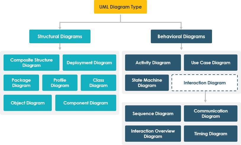
Unified Modeling Language (UML) is a powerful tool used in software engineering to visualize the design of systems. UML diagrams provide a standardized way to represent various aspects of a system, making it easier for developers and stakeholders to understand complex structures and interactions. Visual Paradigm is a comprehensive UML modeling tool that supports a wide range of UML diagrams. In this article, we will introduce 14 types of UML diagrams available in Visual Paradigm, each serving a unique purpose in the modeling process.
1. Class Diagram
The Class Diagram is one of the most commonly used UML diagrams. It represents the static structure of a system by showing the system’s classes, their attributes, methods, and the relationships between them. Class diagrams are essential for object-oriented design.
2. Use Case Diagram
A Use Case Diagram illustrates the functional requirements of a system from the user’s perspective. It shows the interactions between actors (users or other systems) and the system itself, helping to identify the system’s functionalities.
3. Sequence Diagram
The Sequence Diagram is used to model the interactions between objects in a time-ordered sequence. It shows how messages are exchanged between objects and the order in which these interactions occur, making it useful for understanding dynamic behavior.
4. Activity Diagram
An Activity Diagram represents the flow of control or data within a system. It is particularly useful for modeling business processes and workflows, showing the sequence of activities and decision points.
5. State Machine Diagram
The State Machine Diagram describes the states of an object and the transitions between those states. It is useful for modeling the lifecycle of an object and understanding how it responds to various events.
6. Component Diagram
A Component Diagram illustrates the components of a system and their relationships. It helps in visualizing the organization and dependencies among software components, making it easier to manage complex systems.
7. Deployment Diagram
The Deployment Diagram shows the physical deployment of artifacts on nodes. It is useful for understanding the hardware and software environment in which a system operates, including servers, devices, and their connections.
8. Object Diagram
An Object Diagram is a snapshot of the objects in a system at a particular point in time. It shows instances of classes and their relationships, providing a clear view of the system’s state.
9. Package Diagram
The Package Diagram organizes classes into packages, helping to manage large systems by grouping related classes. It shows the dependencies between packages, making it easier to understand the system’s structure.
10. Composite Structure Diagram
A Composite Structure Diagram depicts the internal structure of a class and its interactions with other classes. It is useful for modeling complex classes that contain multiple parts.
11. Interaction Overview Diagram
The Interaction Overview Diagram provides a high-level view of the interactions in a system. It combines elements of activity and sequence diagrams to show how different interactions are organized.
12. Timing Diagram
A Timing Diagram focuses on the timing constraints of messages exchanged between objects. It is useful for modeling real-time systems where timing is critical.
13. Communication Diagram
The Communication Diagram emphasizes the relationships between objects and the messages they exchange. It provides a more flexible view of interactions compared to sequence diagrams.
14. Profile Diagram
A Profile Diagram allows for the extension of UML by defining custom stereotypes, tagged values, and constraints. It is useful for adapting UML to specific domains or methodologies.
Conclusion
Visual Paradigm offers a rich set of UML diagrams that cater to various modeling needs. Understanding these diagrams is essential for effective software design and communication among stakeholders. By utilizing these diagrams, developers can create clear and comprehensive models that enhance the overall development process. For more information on each diagram, visit the respective links provided above.
References
Here’s a list of 14 types of UML diagrams supported by Visual Paradigm, each with an embedded URL for reference:
- Class Diagram
Class Diagram - Use Case Diagram
Use Case Diagram - Sequence Diagram
Sequence Diagram - Activity Diagram
Activity Diagram - State Machine Diagram
State Machine Diagram - Component Diagram
Component Diagram - Deployment Diagram
Deployment Diagram - Object Diagram
Object Diagram - Package Diagram
Package Diagram - Composite Structure Diagram
Composite Structure Diagram - Interaction Overview Diagram
Interaction Overview Diagram - Timing Diagram
Timing Diagram - Communication Diagram
Communication Diagram - Profile Diagram
Profile Diagram
These links provide detailed information about each type of UML diagram available in Visual Paradigm.
