Unified Modeling Language (UML) is a powerful tool for visualizing and designing software systems. This guide explains the key concepts and relationships of use case diagrams, use case templates, flow of events, sequence diagrams, object diagrams, and class diagrams. We will use an example of an online bookstore system to illustrate these concepts.
Use Case Diagram
Purpose: To capture the functional requirements of a system from the user’s perspective.
Components:
- Actors: Represent users or external systems that interact with the system.
- Use Cases: Represent the functionalities or services provided by the system.
- Relationships: Show the interactions between actors and use cases.
Example: In an online bookstore system, actors include “Customer” and “Administrator.” Use cases include “Browse Books,” “Search Books,” “Add to Cart,” “Place Order,” “Manage Inventory,” and “Process Returns.”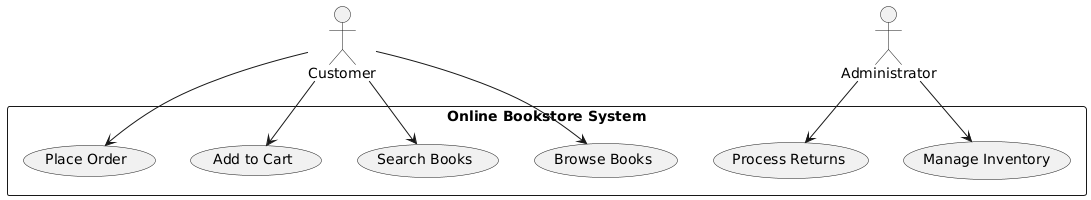
Use Case Templates
Purpose: To document the details of a use case, including its description, actors, preconditions, postconditions, and flow of events.
Components:
- Use Case Name: The name of the use case.
- Actors: The actors involved in the use case.
- Preconditions: Conditions that must be true before the use case starts.
- Postconditions: Conditions that must be true after the use case ends.
- Flow of Events: The sequence of steps performed in the use case.
Example: Use Case Template for “Place Order”
- Use Case Name: Place Order
- Actors: Customer
- Preconditions: The customer must have items in the cart.
- Postconditions: The order is placed, and the inventory is updated.
- Flow of Events:
- The customer selects the “Place Order” option.
- The system validates the items in the cart.
- The system creates an order.
- The system updates the inventory.
- The system sends an order confirmation to the customer.
Flow of Events
Purpose: To describe the sequence of steps performed in a use case.
Components:
- Main Flow: The primary sequence of steps.
- Alternative Flows: Alternative sequences of steps for different conditions.
- Exception Flows: Sequences of steps for handling exceptions.
Example: Flow of Events for “Place Order”
-
Main Flow:
- The customer selects the “Place Order” option.
- The system validates the items in the cart.
- The system creates an order.
- The system updates the inventory.
- The system sends an order confirmation to the customer.
-
Alternative Flow:
- If the validation fails, the system notifies the customer.
-
Exception Flow:
- If the inventory update fails, the system notifies the administrator.
Sequence Diagram
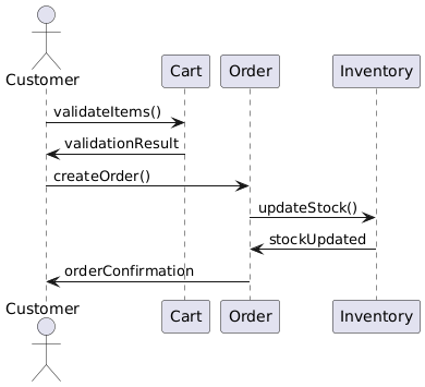
Purpose: To model the dynamic behavior of a system by showing how objects interact over time.
Components:
- Objects: Represent instances of classes.
- Messages: Represent the interactions between objects.
- Lifelines: Show the existence of objects over time.
Example: Sequence Diagram for “Place Order”
Object Diagram
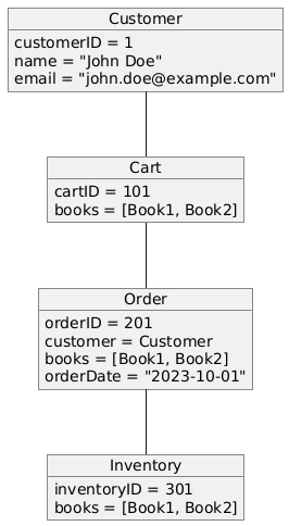
Purpose: To provide a snapshot of the system at a specific point in time, showing objects and their relationships.
Components:
- Objects: Instances of classes.
- Links: Relationships between objects.
Example: Object Diagram for “Place Order”
Class Diagram
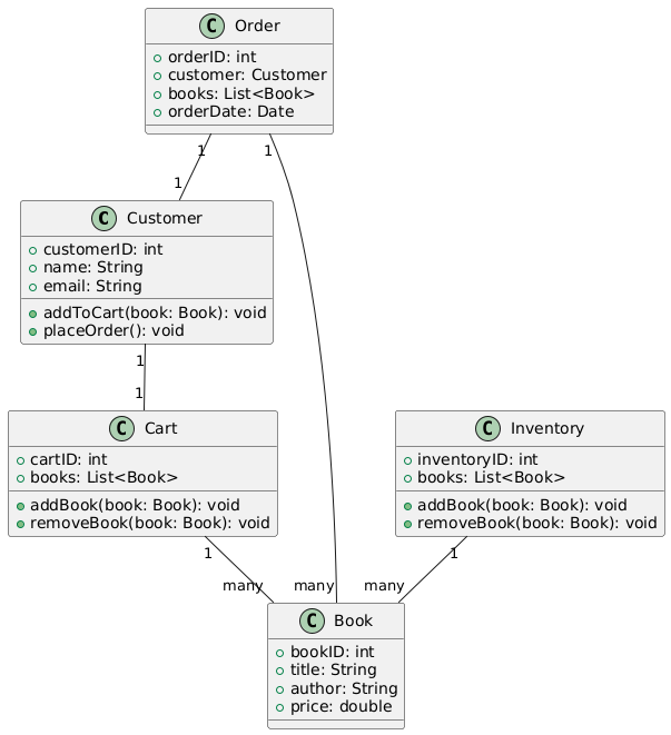
Purpose: To model the static structure of a system by showing its classes, attributes, methods, and relationships.
Components:
- Classes: Represent the entities in the system.
- Attributes: Represent the properties of the classes.
- Methods: Represent the behaviors of the classes.
- Relationships: Show the associations, inheritance, and dependencies between classes.
Example: Class Diagram for Online Bookstore System
Integrating the Diagrams
- Use Case Diagram: Identifies the high-level functionalities of the system.
- Use Case Templates: Document the details of each use case.
- Flow of Events: Describes the sequence of steps in a use case.
- Sequence Diagram: Models the dynamic interactions between objects for a specific use case.
- Object Diagram: Provides a snapshot of the system at a specific point in time.
- Class Diagram: Defines the static structure of the system.
By integrating these diagrams, you can capture the requirements, design the system structure, and model the interactions, providing a comprehensive view of the system.
Conclusion
Understanding the key concepts and relationships of use case diagrams, use case templates, flow of events, sequence diagrams, object diagrams, and class diagrams is essential for effective software design. These diagrams complement each other, providing a holistic view of the system’s requirements, structure, and behavior. By following this guide and the example of an online bookstore system, you can effectively use these diagrams to design and develop robust software systems.
