Introduction
UML (Unified Modeling Language) Activity Diagrams are essential tools for modeling dynamic behaviors of a system. They visually represent workflows of stepwise activities and actions, making complex processes easier to understand and communicate. This guide will walk you through the fundamentals of UML Activity Diagrams, provide practical examples using PlantUML, and highlight the benefits of learning by examples.
Key Concepts
1. Activities and Actions
- Activities: These are the primary components of an Activity Diagram, representing individual steps or operations within a process.
- Actions: These are atomic activities that cannot be further decomposed.
2. Control Flow
- Control Flow: This indicates the sequence of activities, shown using arrows that connect activities to illustrate the order of execution.
3. Initial and Final Nodes
- Initial Node: Marks the starting point of the workflow, represented by a solid circle.
- Final Node: Marks the ending point of the workflow, represented by a bullseye symbol (a circle within a circle).
4. Decision and Merge Nodes
- Decision Node: A point where the flow branches based on a condition, represented by a diamond shape.
- Merge Node: A point where multiple flows converge back into a single flow, also represented by a diamond shape.
5. Swimlanes
- Swimlanes: Used to organize activities into groups, typically representing different roles or responsibilities. They are depicted as vertical or horizontal lanes.
Benefits of Learning by Examples
Learning by examples offers several advantages:
- Practical Understanding: Seeing real-world applications helps in grasping the concepts more effectively.
- Visual Learning: Diagrams provide a visual representation, making it easier to understand complex processes.
- Immediate Application: Examples can be directly applied to similar scenarios, enhancing problem-solving skills.
- Engagement: Examples make the learning process more engaging and interactive.
- Contextual Learning: Examples provide context, helping to understand how different concepts fit together in a real-world setting.
Examples
Example 1: Simple Order Processing
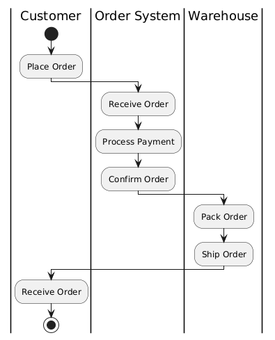
Explanation:
- The process starts with the customer placing an order.
- The order system receives the order, processes the payment, and confirms the order.
- The warehouse then packs and ships the order.
- Finally, the customer receives the order.
Example 2: ATM Withdrawal Process
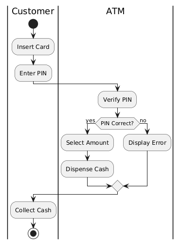
Explanation:
- The customer inserts the card and enters the PIN.
- The ATM verifies the PIN. If correct, the customer selects the amount and the ATM dispenses the cash. If incorrect, the ATM displays an error.
- The customer collects the cash.
Example 3: Library Book Borrowing
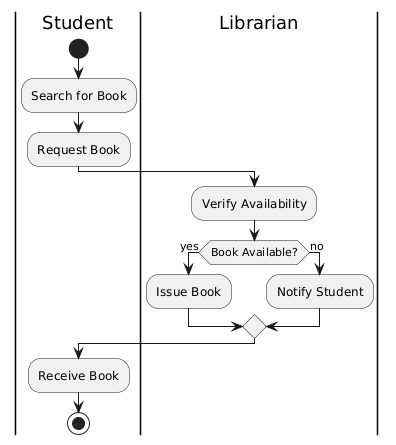
Explanation:
- The student searches for a book and requests it.
- The librarian verifies the availability. If the book is available, the librarian issues the book. If not, the librarian notifies the student.
- The student receives the book.
Example 4: Online Shopping
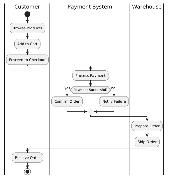
xplanation:
- The customer browses products, adds them to the cart, and proceeds to checkout.
- The payment system processes the payment. If successful, the order is confirmed. If not, the customer is notified of the failure.
- The warehouse prepares and ships the order.
- The customer receives the order.
Example 5: Hotel Booking
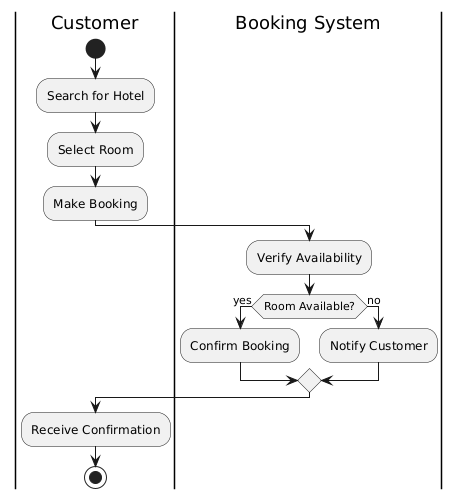
Explanation:
- The customer searches for a hotel, selects a room, and makes a booking.
- The booking system verifies the availability. If the room is available, the booking is confirmed. If not, the customer is notified.
- The customer receives the confirmation.
Interpreting UML Activity Diagrams
- Flow of Activities: Follow the arrows to understand the sequence of activities. Each arrow represents the flow of control from one activity to the next.
- Decision Points: At decision nodes, evaluate the condition to determine which branch to follow. This helps in understanding different scenarios based on conditions.
- Swimlanes: Identify the roles or responsibilities associated with each swimlane. This helps in understanding who is responsible for each activity.
- Initial and Final Nodes: The initial node indicates the starting point of the process, while the final node indicates the end point.
- Concurrency: Look for forks and joins to understand parallel activities. Forks split the flow into concurrent activities, while joins synchronize them back into a single flow.
Conclusion
UML Activity Diagrams are a versatile tool for modeling and understanding complex processes. By using these diagrams, you can easily create and visualize workflows, making it simpler to communicate and analyze processes. Whether you are designing a new system or documenting an existing process, Activity Diagrams provide a clear and structured way to represent dynamic behaviors. Learning by examples enhances your understanding and application of these diagrams, making you more proficient in using them for real-world scenarios.
References
- Activity Diagram, UML Diagrams Example: Swimlane
- A Guide to Swimlane Activity Diagrams
- How to Draw Activity Diagram?
- Activity Diagram, UML Diagrams Example: Swinlane Proposal Process
- How to Draw an Activity Diagram in UML?
- Activity Diagram Tutorial
- What is Activity Diagram?
- Activity Diagram 2 with Swimlanes
- Activity Diagram, UML Diagrams Example: Swimlane for Order Fulfilment
- ATM Activity Diagram with Swimlanes