


Creating a use case diagram is a crucial step in software development and systems analysis. Use case diagrams help visualize the functional requirements of a system, showing the interactions between users (actors) and the system (use cases). Visual Paradigm is a powerful tool that can assist in creating these diagrams efficiently. Below is a comprehensive guide to creating use case diagrams, including recommendations for using Visual Paradigm.
1. Introduction to Use Case Diagrams
A use case diagram is a type of behavioral diagram defined by the Unified Modeling Language (UML). It consists of:
- Actors: Represent users or other systems that interact with the system being modeled.
- Use Cases: Represent the functional requirements or behaviors of the system.
- Relationships: Show the interactions between actors and use cases, as well as relationships between use cases themselves.
2. Identifying Use Cases
To identify use cases, follow these steps:
- Identify Actors: Determine who or what will interact with the system. Actors can be users, other systems, or hardware.
- Determine Goals: For each actor, identify what they want to achieve with the system. These goals become use cases.
- Define Use Cases: Describe each use case in detail, including preconditions, postconditions, main success scenario, and extensions (alternative paths).
Example
For a restaurant management system, actors might include:
- Waiter
- Chef
- Patron
- Cashier
Goals for the Waiter actor might include:
- Order Food
- Order Wine
- Serve Food
- Serve Wine
3. Characteristics of Good and Bad Use Cases
Good Use Cases
- Clear and Concise: Easy to understand and unambiguous.
- User-Focused: Describes what the user wants to achieve, not how the system will achieve it.
- Complete: Includes all necessary information, such as preconditions, postconditions, and alternative paths.
- Independent: Can be understood and implemented independently of other use cases.
Bad Use Cases
- Vague: Lacks clarity and specificity.
- Technical: Focuses on implementation details rather than user goals.
- Incomplete: Missing important information or scenarios.
- Dependent: Relies heavily on other use cases, making it difficult to understand in isolation.
4. Levels of Use Cases
Use cases can be categorized into different levels based on their scope and detail:
- Summary Level (User Goals): High-level use cases that describe the main goals of the actors.
- Primary Level (User Goals): More detailed use cases that break down the summary level use cases into smaller, more manageable goals.
- Subfunction Level (Sub-Goals): Detailed use cases that describe the steps required to achieve the primary level use cases.
Example
For a restaurant management system:
- Summary Level: Manage Orders
- Primary Level: Order Food, Order Wine
- Subfunction Level: Serve Food, Serve Wine
5. Using Levels in Use Case Diagrams
When creating a use case diagram, start with the summary level use cases and then break them down into primary and subfunction level use cases as needed. This hierarchical approach helps in managing complexity and ensuring that all functional requirements are captured.
Steps
- Create Summary Level Use Cases: Identify the main goals of the actors.
- Break Down into Primary Level Use Cases: For each summary level use case, identify the smaller goals that need to be achieved.
- Detail Subfunction Level Use Cases: For each primary level use case, describe the steps required to achieve the goal.
6. Relationships Between Use Cases and Actors
Use cases and actors are connected through relationships:
- Association: A line connecting an actor to a use case, indicating that the actor participates in the use case.
- Include: A relationship between use cases where one use case includes the behavior of another use case.
- Extend: A relationship between use cases where one use case extends the behavior of another use case under certain conditions.
- Generalization: A relationship between actors or use cases where one actor or use case is a specialization of another.
Example
In a restaurant management system:
- Association: Waiter — Order Food
- Include: Serve Food — Cook Food
- Extend: Order Food — Order Wine (if requested)
- Generalization: Cashier — Supervisor (where Supervisor is a type of Cashier)
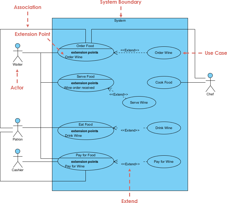
7. Example Use Case Diagram
Let’s create a use case diagram for a restaurant management system.
Actors
- Waiter
- Chef
- Patron
- Cashier
Use Cases
- Waiter
- Order Food
- Order Wine
- Serve Food
- Serve Wine
- Chef
- Cook Food
- Patron
- Eat Food
- Drink Wine
- Cashier
- Pay for Food
- Pay for Wine
Relationships
- Association: Waiter — Order Food, Order Wine, Serve Food, Serve Wine
- Include: Serve Food — Cook Food
- Extend: Order Food — Order Wine (if requested)
- Generalization: Cashier — Supervisor (where Supervisor is a type of Cashier)
Diagram
8. Using Visual Paradigm for Use Case Diagrams
Visual Paradigm is a powerful tool for creating use case diagrams. Here’s how you can use it:
- Create a New Project: Open Visual Paradigm and create a new project.
- Select Use Case Diagram: Choose the use case diagram from the available diagram types.
- Add Actors: Use the actor tool to add actors to your diagram.
- Add Use Cases: Use the use case tool to add use cases to your diagram.
- Define Relationships: Use the association, include, extend, and generalization tools to define relationships between actors and use cases.
- Organize Layout: Use the layout tools to organize your diagram vertically or horizontally for better readability.
- Save and Export: Save your diagram and export it in various formats (e.g., PNG, PDF) for documentation or presentation purposes.
Tips for Using Visual Paradigm
- Use the Modeling Assistant: Visual Paradigm provides a modeling assistant that can help you with suggestions and corrections as you create your diagram.
- Leverage Templates: Use pre-defined templates to speed up the creation of your use case diagrams.
- Collaborate: Visual Paradigm supports team collaboration, allowing multiple users to work on the same diagram simultaneously.
Conclusion
Creating a use case diagram involves identifying actors and use cases, defining their relationships, and organizing them into levels of detail. Good use cases are clear, user-focused, complete, and independent, while bad use cases are vague, technical, incomplete, and dependent. By following these guidelines and using a tool like Visual Paradigm, you can create effective use case diagrams that capture the functional requirements of your system.
Use Case References
Here is a reference list on use case diagrams using the Visual Paradigm UML tool
-
Introduction to UML Diagrams in Visual Paradigm – ArchiMetric
- This article introduces 14 types of UML diagrams available in Visual Paradigm, including use case diagrams. It explains how each diagram serves a unique purpose in the modeling process and provides detailed information about each type of UML diagram available in Visual Paradigm.
- Read more
-
Online Use Case Diagram Tool
- Visual Paradigm Online provides an easy-to-use online UML diagram maker with a rich set of customizable use case diagram examples. It allows users to create professional use case diagrams quickly with a drag-and-drop editor and collaborate with their team in a cloud workspace.
- Read more
-
Free UML Tool
- This free UML modeling tool supports 13 UML 2.x diagrams and ERD diagrams for non-commercial purposes. It is used by over 1 million installations globally and helps in identifying the business goals of a system through use case diagrams.
- Read more
-
Free Use Case Diagram Tool
- Visual Paradigm Online offers a free web-based use case diagram editor that supports UML, ERD, and Organization Chart diagrams. It allows users to draw use case diagrams quickly through an intuitive UML drawing editor without any limitations on the number of shapes or diagrams.
- Read more
-
How to Draw Use Case Diagram?
- This guide provides step-by-step instructions on how to draw use case diagrams in Visual Paradigm. It explains how to model system functions and actors that interact with those functions using the UML tool.
- Read more
-
Use Case Description in Visual Paradigm for UML
- Visual Paradigm for UML (VP-UML) is a UML CASE tool designed for software engineers, system analysts, business analysts, and system architects. It helps in building large-scale software systems reliably through the use of the object-oriented approach.
- Read more
-
Use Case Diagram – UML 2 Diagrams – UML Modeling Tool
- This article explains how to create use case diagrams to describe the behavior of the target system from an external point of view. Visual Paradigm allows users to document the requirements through use case descriptions.
- Read more
-
Online UML Diagram Tool
- Visual Paradigm Online supports various UML diagrams, including use case diagrams. It features powerful diagramming tools, on-the-fly UML syntax checks, and a neat user interface, allowing users to draw UML diagrams effortlessly.
- Read more
These references provide a comprehensive overview of creating and using use case diagrams with the Visual Paradigm UML tool.
